
Studer A810 explained
The information below was derived from my Studer A810 2-channel Time Code model with 3 tape speeds and built-in Volume Unit Meters. Some of this information may therefore not be applicable to other A810 tape recorder models, which exist in 24 different versions. For detailed information always follow the instructions of your Studer A810 Operating Manual.
Wolfgang Bleier, Austria
November 2008
It was the year 1982 when Studer Revox has first presented the Studer A810 tape recorder. In this year Studer Revox has moved to its new administration and manufacturing facility in Regensdorf nearby Zürich, and the company Willi Studer was changed into the stock corporation Studer Revox AG. The Studer A810 tape recorder was last built in the year 1989.
 By virtue of its compact, sturdy construction, inherent system flexibility, and the operating convenience achieved by the incorporation of microprocessors, the STUDER A810 tape recorder was universally suited for Broadcasting and Television applications, for use in Studios or OB vans, in Theatres, Film studios, and Scientific Institutes.
Alike other Studer tape recorders, a rigid, die cast light-alloy chassis for tape transport, head block, pressure unit, and other assemblies make the A810 extremely solid and reliable, essentially being also a symbol for robust and fine audio tape recorders.
Capstan motor servo control with crystal-controlled reference and capacitive sensors for highly accurate tape speed, or gentle tape processing through electronically controlled tape tension with servo controlled AC spooling motors and breaker less tape tension sensors are just some of the features that give this recorder a reputation of excellent engineering. It is available with up to 4 tape speeds from 9,5 cm/s to 76 cm/s (4,75 to 30 ips), and with its switchable AC line voltage of 100, 120, 140, 200, 220 or 240 Volts and mains frequencies of 50 or 60 Hz it can operate in the most remote places on this planet.
By virtue of its compact, sturdy construction, inherent system flexibility, and the operating convenience achieved by the incorporation of microprocessors, the STUDER A810 tape recorder was universally suited for Broadcasting and Television applications, for use in Studios or OB vans, in Theatres, Film studios, and Scientific Institutes.
Alike other Studer tape recorders, a rigid, die cast light-alloy chassis for tape transport, head block, pressure unit, and other assemblies make the A810 extremely solid and reliable, essentially being also a symbol for robust and fine audio tape recorders.
Capstan motor servo control with crystal-controlled reference and capacitive sensors for highly accurate tape speed, or gentle tape processing through electronically controlled tape tension with servo controlled AC spooling motors and breaker less tape tension sensors are just some of the features that give this recorder a reputation of excellent engineering. It is available with up to 4 tape speeds from 9,5 cm/s to 76 cm/s (4,75 to 30 ips), and with its switchable AC line voltage of 100, 120, 140, 200, 220 or 240 Volts and mains frequencies of 50 or 60 Hz it can operate in the most remote places on this planet.
The Studer A810 has started the era of programmable, digital control functions in small studio recorders. It combines compact dimensions suitable for 19’’ racks with kind of intelligence that was not known on tape recorders before the eighties. It has a serial BUS interface, allows remote digital alignment, performs self-diagnosis routines and is also available with time-code synchronization. Once its operating panel is folded up, it offers extensive possibilities for programming of individual functions, and there is almost nothing that cannot be altered in respect to operation, key functions for tape handling or its audio parameters.
 The Locator-Keys on the Command Unit are programmable for a number of different functions, which makes this recorder highly flexible for any kind of application in studios and broadcasting facilities.
Behind the foldable operating panel you’ll find almost all electronics of the audio circuits and tape recorder controls clearly arranged on plug-in boards, accessible for programming, audio setup as well as maintenance. The audio parameters can be set for up to four tape speeds, two different tapes and for NAB or CCIR equalization. It is advisable to have the A810 equipped with the connector for serial remote control (10) and the address board (11), in order that its audio parameters can be saved on tape mounted on the same machine of which the audio parameters are to be saved, or on a tape mounted on another tape recorder or a cassette deck. This feature makes this recorder most flexible for use of different tape specifications, or for re-load of the audio parameters in case these got lost due to a weak RAM buffer battery.
The Locator-Keys on the Command Unit are programmable for a number of different functions, which makes this recorder highly flexible for any kind of application in studios and broadcasting facilities.
Behind the foldable operating panel you’ll find almost all electronics of the audio circuits and tape recorder controls clearly arranged on plug-in boards, accessible for programming, audio setup as well as maintenance. The audio parameters can be set for up to four tape speeds, two different tapes and for NAB or CCIR equalization. It is advisable to have the A810 equipped with the connector for serial remote control (10) and the address board (11), in order that its audio parameters can be saved on tape mounted on the same machine of which the audio parameters are to be saved, or on a tape mounted on another tape recorder or a cassette deck. This feature makes this recorder most flexible for use of different tape specifications, or for re-load of the audio parameters in case these got lost due to a weak RAM buffer battery.
)
In 1983 Studer's order list of the A810 has shown 24 different versions, with additional 12 options for extension and a considerable number of accessories. Thanks to its outstanding performance and flexibility, this recorder was considered among the best of mastering machines for a long time.
Nowadays the A810s are often sorted out by professional broadcasting and recording studios, and some of these recorders have outlasted decades in excellent condition. It’s no wonder that these swiss-made masterpieces became highly desired items, and, if you can get a well preserved A810, you’ll have the luxury of a professional studio mastering recorder for your personal use.
Below I have summarized important features, some useful tips as well as references to the Studer A810 Operating Manual that appeared practical to me for the operation of the A810 in my private home studio.
Important Features
AC Power, Voltage Selector (100, 120, 140, 200, 220 or 240 V)
Verify the setting of the voltage selector every time after transport and/or service works to match the local line voltage (240V).
Self-Diagnosis & Data Display after Power ON
For example display of 0188 indicates the calendar week and the year (week 1 in 1988) of the Software release date, followed by display of the tape address at the last switch off.
Spooling Speeds
Spooling speeds are 10 (standard), 7, 4 and 1 m/sec. When spooling at standard speed press the key sequence TRANS ◄ or TRANS ► to decrease the spooling speed to 7 m/sec. Pushing again the key ◄ or ► will reduce the spooling speed to the next lower level. From STOP or PLAY mode start spooling immediately at the lowest speed by pressing the key sequence TRANS ► or TRANS ◄. Spooling at full speed can be resumed by pressing TRANS (or STOP or PLAY).
Symptoms that you may experience with too slow standard spooling speed:
Should your recorder spool at too low standard speed in spite of correct mechanic adjustment of the tape tension sensors, a moderate (electrical) reduction of the tape tension for the rewind and forward mode, by adjusting the respective trimmer potentiometers on the tape deck controller (Studer Manual 3.4.5), can provide better spooling results. Before doing this you should verify, and if necessary mechanically re-adjust, the force on the left and right hand tape tension sensors (Studer Manual 3.3).
Select Tape A / B
Press STOP and Tape A/B key simultaneously to select Tape A or B.
Select NAB/CCIR Equalization
Press STOP and NAB/CCIR key simultaneously. The code switch JS7 on the Periphery-Controller has to be in position JS7=0, otherwise (at JS7=1) the audio parameters will be the same for NAB and CCIR equalization.
VU-Meter
VU or PPM mode can be individually selected with the jumpers on the back of the VU meters (Studer Manual 4.2.9.5).
Replacement of the VU-meter light bulbs:
Remove all four screws from the VU-meter's front panel (taking out the VU-meter will be easier if you remove also the screws of the other VU-meter).
Take out the VU-meter carefully, lift it up and unscrew the hexagon socket head cap screw located in the center of the circuit board at the back side of the meter. Detaching the circuit board at the back side can be tricky: widen the plastic snap-lock system holding the circuit board and and remove the board. Remember that the snap-lock can break when trying to detach the circuit board, and that contact pins of that circuit board are connected to a plug-in base mounted on another circuit board.
It will be a good idea to replace both light bulbs on both VU meter assemblies all at one time - these bulbs will last for many years.
Display of stored LOC Addresses
Press STOP and respective LOC key simultaneously (LOC1, LOC2 or LOC START,…)
Display of Recorder’s operating hours
Press TRANS and ZERO LOC simultaneously.
Tape Dump (waste basket operation)
When starting tape dump operation, pull the tape to the right. Pressing TAPE DUMP again, or STOP, switches off the tape dump mode.
Cleaning the Tape Path
Cleaning of the tape path can be done as usual on any other tape recorder. For cleaning of the scrape flutter roller see your Studer Manual, 2.9.
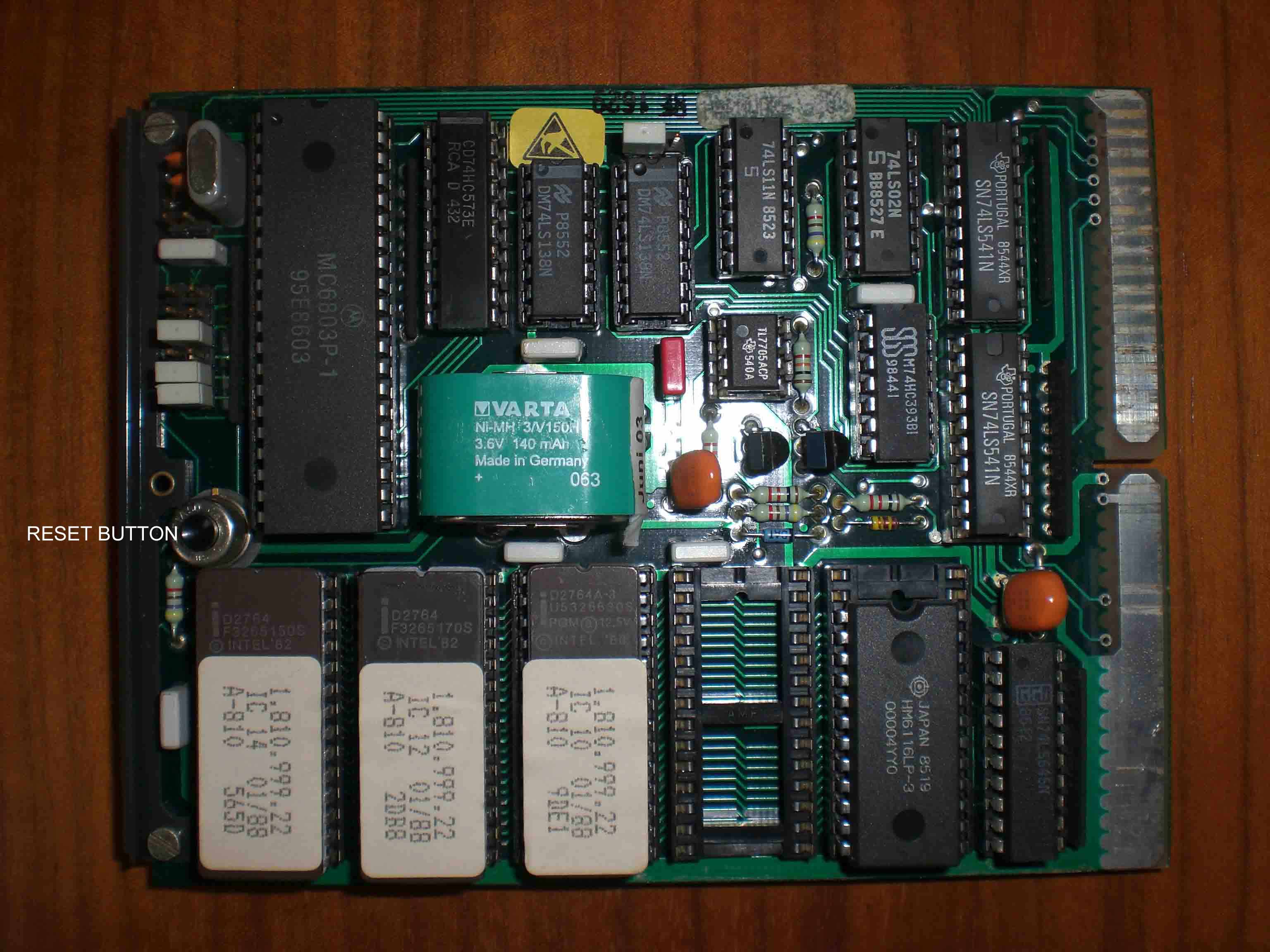
RAM Buffer Battery (BA1)
Studer Manual 2.7 and 2.7.1 (degraded operation), 3.1.2 (MP Unit), and Section 5 (MP Unit diagrams).
Check the accumulator occasionally and refresh if necessary, or replace it after a couple of years. Something very important: before you replace the accumulator make a backup of your recorder's audio parameters, which you can re-load to your recorder after you have replaced the accumulator! The accu-pack is soldered on the MP Unit. Concerning the accumulator type refer to the MP-Unit diagrams in Section 5 of your Studer Manual.
Should you use your recorder only once in a while it may be necessary that you leave it switched on for a day (or during the night) about once a week to charge the accumulator, in order to avoid complete loss of the audio parameters to which your tape recorder was calibrated. If you do this with a Studer A810 it will be a good idea to set the jumper JS2 on the Capstan Motor Control print to the position "Capstan Shut Off", which will protect the bearings of the capstan motor from unnecessary wear - for more details see also below.
My recorder has a Varta Ni-MH 3/V150H 3,6V 140mAh accu installed (3 x 1,2V cells, 140 mAh each, assembled to an accu-pack). Supply sources in central Europe: VRI GmbH, Wilhelm - Maybach - Strasse 4, D-73479 Ellwangen, or one of the stores of Conrad Electronic GmbH & Co KG. For more details about the RAM buffer battery in a Studer A810 read this Essay.
Capstan Motor
Studer Manual 2.9, 3.2.9, 3.4.6, 4.2.9.12, and Section 6 (Tape Transport Diagrams)
In order to save the bearings of the capstan motor from unnecessary wear and tear, the jumper JS2 on the capstan motor control print (Capstan Motor Control PCB / GR26) can be set in the position CAPSTAN SHUT OFF as shown below. When JS2 is in position CAPSTAN SHUT OFF the capstan motor will switch off in case of „Tape Out“.
 JS2 on the capstan motor control print is accessible from the rear of the recorder by using pincers. Handle cautiously in order not to loose the jumper.
Cleaning of the capstan shaft: The capstan motor normally does not rotate in this position of JS2 when no tape is threaded. For cleaning of the capstan shaft the left-hand tape tension sensor is to be lifted slightly; the capstan motor will then rotate until the recorder is switched off or any of the tape command keys (except STOP) is pressed.
Programming of the operating parameters
(Studer Manual 3.1.6,3.5.7, 4.2.9, or see the diagram at the backside of the foldable operating panel)
Various Operating Parameters of the tape recorder and the LOC Function Keys can be programmed with the code-switches JS 0 ... JS 19. The 20 code-switches are accessible on the rear of the Command Unit.
Note: After the operating parameters of the Command Unit have been changed a microprocessor reset must be initiated. Press the re-set push button on the MP-Unit, or switch off the recorder and switch on again after 5 seconds.
Locator Function Keys
Programming of the key functions is done with JS13-19 (see the table in your Studer Manual, or the diagram at the backside of the foldable operating panel). The following programming of the LOC function keys I’ve found quite useful:
LOC 1 = Saves a tape address. Press key sequence TRANS & LOC1 to save a tape address (press the key LOC1 only to spool the tape to the address saved)
LOC 2 = LOCSTART spools the tape to the address of the last Play or Record start position
LOC 3 = LIFTER to lift the tape lift pins
LOC 4 = TAPE DUMP for waste basket operation
To program the above functions the settings are: JS13 – JS19 = 1 1 0 0 0 1 0.
Of course all 4 LOC function keys can be programmed for saving tape addresses, same as LOC1. In this case the settings are: JS13 – JS19 =0.
Drop-In / Drop-Out (Start Record / Start Play Mode)
Drop-In (from Play mode): my current settings require pressing of the REC+PLAY keys (JS12=1).
JS12=0 direct drop-in with REC key only.
JS12=1 drop-in with REC+PLAY
Drop-In / Drop-Out: the machine can be set that Erase- and Record heads are switched simultaneously, or with time offset in consideration of the tape speed to compensate the tape movement. With time offset: JS4=0 JS5=0. Simultaneously: JS4=1 JS5=1. (see also your Studer Manual 3.1.6, 3.5.7, 4.2.9) The settings on my recorder are for time offset.
Lifter
Lifter key mode can be set with JS3: JS3=0 Momentary-key, JS3=1 Flip-Flop key
Tape Type Selector - Tape A/B
Settings are made with JS6, JS7 and JS8 (refer to tables in Studer Manual 4.2.9, or to the backside of the foldable operating panel). The key on the Master Panel of my recorder is programmed for selecting the Tape Type (JS6=0, JS7 and JS8 therefore have no effect)
Operating Parameters that I have currently programmed
(Setting of all code switches JS0 …. JS19)
| Bank | Code Switch | Position | Description |
| 0 | JS 00 | ON | Time Code Mode |
| 1 | JS 01 | OFF | Time Code Mode |
| 2 | JS 02 | ON | Time Code Mode |
| 3 | JS 03 | OFF | Lifter Key (set for momentary mode) |
| 4 | JS 04 | OFF | Drop Out - Rec. & Play head w. time offset (enabled) |
| 5 | JS 05 | OFF | Drop In - Rec. & Play head w. time offset (enabled) |
| 6 | JS 06 | OFF | Tape Type Selection (by push buttons on the master panel) |
| 7 | JS 07 | OFF | Tape Type Selection (no effect) |
| 8 | JS 08 | OFF | Tape Type Selection (no effect) |
| 9 | JS 09 | OFF | Tape Speed (set for 3-speed LS version) |
| 0 | JS 10 | OFF | Tape Speed (set for 3-speed LS version) |
| 1 | JS 11 | OFF | Tape Speed (set for 3-speed LS version) |
| 2 | JS 12 | ON | Drop-In (from play to record mode with REC+PLAY keys) |
| 3 | JS 13 | ON | Programmable Keys (LOC/Function Keys - see above) |
| 4 | JS 14 | ON | Programmable Keys (LOC/Function Keys - see above) |
| 5 | JS 15 | OFF | Programmable Keys (LOC/Function Keys - see above) |
| 6 | JS 16 | OFF | Programmable Keys (LOC/Function Keys - see above) |
| 7 | JS 17 | OFF | Programmable Keys (LOC/Function Keys - see above) |
| 8 | JS 18 | ON | Programmable Keys (LOC/Function Keys - see above) |
| 9 | JS 19 | OFF | Programmable Keys (LOC/Function Keys - see above) |
Important:
After changing the operating parameters of the Command Unit a microprocessor reset must be initiated. Press the re-set push button on the MP-Unit, or switch off the recorder and switch on again after 5 seconds.
Backup of the audio parameters & re-load (Summary)
(Studer Manual 2.8, 2.8.2, 3.5.8, 4.2.7, 4.2.8)
After calibration the audio parameters can be saved (recorded) on a tape mounted on the same machine of which the audio parameters are to be saved, or on a tape mounted on another tape recorder or a cassette deck. For backup and re-load of the audio parameters you will need 2 symmetrical audio cables, each with a serial and a XLR (or RCA/Chinch) connector configured according to the Studer Manual 4.2.7 and 4.2.8. One cable is for Backup (recording), the other one for Verification and Re-Load (replay) of the audio parameters. For easier identification I've made the cable for backup in red, and the cable for verification and re-load in green color.
Either operation (backup, verification or re-load) requires correct setting of JS 1 to 8 of the address board (11) on the upper side of the recorder as indicated below. Release the UNCAL buttons before backup, verification or re-load. The recorder automatically performs 3 backup cycles; for re-load of the audio parameters replay of one backup cycle is sufficient. Please consider that below mentioned message codes relate to recorders with LED timer display. Important: After switching JS 1-8 on the address board you must perform a re-set on the MP-Unit, or switch off and on (after 5 seconds) the recorder. Consider that the information below is a summary; therefore you should compare all preparations and steps during backup, verification and re-load with the instructions of your Studer Manual.
| SAVE | RED CABLE | 9 PIN SERIAL on CH1 IN (=RECORD) |
| ADDRESS BOARD | JS 1-7 = 0000000 (OFF) | |
| JS 8 = 1 (ON) | ||
| Release UNCAL buttons. Press READY button | ||
| Save audio parameters (REC + PLAY key) | ||
| MESSAGES | C0C0C (SAVING IN PROGRESS) | |
| CCCCC (SAVING = OK) | ||
| EEE07 (ERROR IN DATA TRANSMISSION) | ||
| VERIFY | GREEN CABLE | 9 PIN SERIAL on CH1 OUT (=PLAY) |
| ADDRESS BOARD | JS 1-7 = 0000000 (OFF) | |
| JS 8 = 1 (ON) | ||
| Release UNCAL buttons | ||
| Perform verification by means of replay (PLAY key) | ||
| MESSAGES | D0D0D (VERIFICATION IN PROGRESS) | |
| DDDDD (VERIFICATION = OK) | ||
| EEE08 (ERROR = DATA CORRUPTED) | ||
| RE-LOAD | GREEN CABLE | 9 PIN SERIAL on CH1 OUT (=PLAY) |
| ADDRESS BOARD | JS 1-6 = 111111 (ON) | |
| JS 7 = 0 (OFF) | ||
| JS 8 = 1 (ON) | ||
| Release UNCAL buttons | ||
| Perform re-load by means of replay (PLAY key) | ||
| MESSAGES | B0B0B (RE-LOAD IN PROGRESS) | |
| BBBBB (RE-LOAD = OK) | ||
| EEE06 (ERROR IN DATA TRANSMISSION) | ||
Important: When making the backup of the audio parameters make sure you’ll always press the REC key first followed by PLAY, until both keys are pressed, otherwise the machine may start in verify- or reload mode.
Before making a backup or re-load of the audio parameters of your Studer A810 compare the above steps with the instructions of your Studer Manual (Sections 2.8 / 3.1.7 / 3.5.8 / 4.2.7 / 4.2.8).
Note: I could successfully save the audio parameters of my recorder only at the tape speed of 9,5 cm/sec (at 19 cm/sec. the error code EEE08 was displayed).